Aqualisa’s Technical Product Trainer, David May, provides a step-by-step guide to installing the exposed Aqualisa Q shower.
Aqualisa Q is the company’s latest smart shower range, designed to provide a completely personalised shower experience every time.
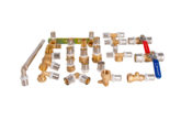
Step 1: Pack contents
Check you have all the pack contents listed below:
- Fixing template
- Riser rail
- Vita shower head
- Shower hose
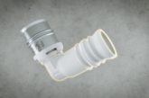
- 90° Push fit elbow
- PINCH GRIP
- Data cable (already fitted to rail)
- Gel holder
- Controller back plate
- Data cable removal tool
- CANBUS converter
- Top rail bracket
- Rail insert cover plate
- Accent ring (in the colour of your choice)
- Q smart controller
- CANBUS data cable
- Ceiling cover plate
Step 2: Smart valve set up
Choose a convenient location for the Aqualisa smart valve; this must be made accessible for future servicing. The smart valve can be sited up to 10 metres from the Q control in locations such as the loft, under a bath or in an airing cupboard. Secure the smart valve and connect the hot and cold pipes.
Step 3: Control positioning
Using a spirit level, attach the template provided, locate the rail and control, position, and drill where stated. It is important to note that the Aqualisa Q controller must be of a suitable height for all members of the household. The proximity sensor on the system will not be able to activate itself otherwise.
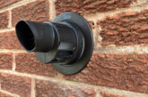
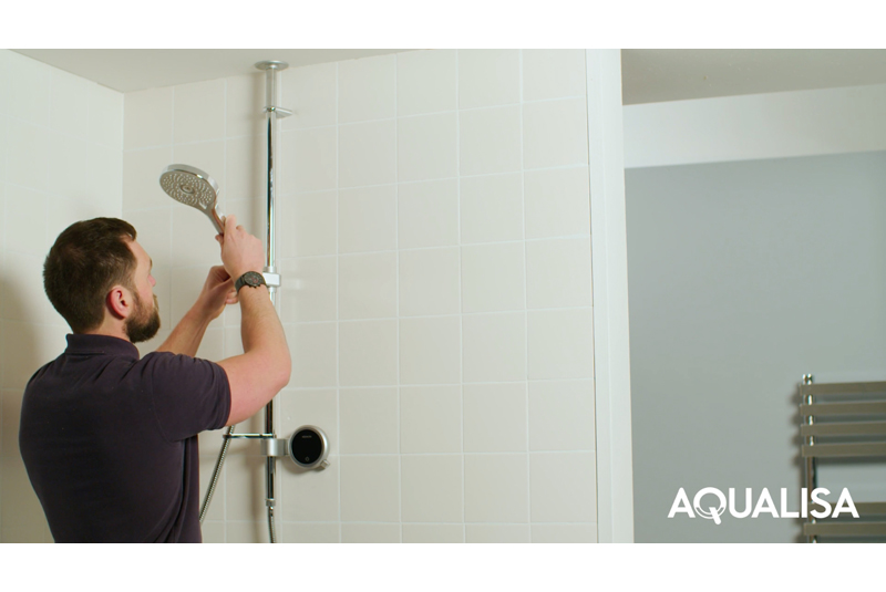
Step 4: Rail installation
Drill a hole in the ceiling of about 30 to 40mm in diameter. Feed the data cable followed by the rail assembly (that contains the supply pipe) through the hole in the ceiling. Then secure to the finished wall with the screws provided.
Step 5: Fitting the control
Attach the rail to the wall as directed, and fit the Q control. The control should be fitted with the power symbol at the seven o’clock position. Gently apply pressure to the screen with one hand, and use the other hand to rotate the controller with the Q lever until it fits into place.
Step 6: Connecting the CANBUS converter
Remove the top case of the Q smart valve and insert the 500mm black CANBUS data cable into the joist/board with self-tapping screws provided. Open the cable connections to the CANBUS with the removal tool provided and connect the 10m data cable to the CANBUS converter box, following the wiring order shown on the label. Secure the CANBUS converter box.
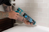
Step 7: Attaching outlets
Flush water through the outlet before connecting to the hose or handset. Use the pivot hose connector to secure the components and lock them into position. Attach carefully to the rail.
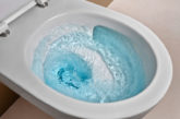
Step 8: Configuration
The shower is now ready to use (once the supplies are switched on). The Q controller can then be easily configured, where a preferred first and secondary outlet can be selected.
For more information, visit www.aqualisa.co.uk. For details of the company’s free training days, visit www.aqualisa.co.uk/training.