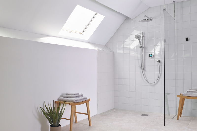
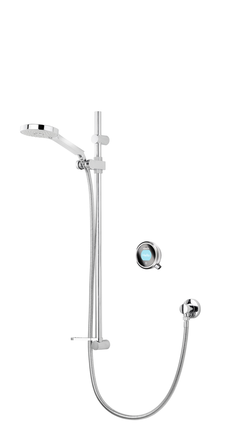
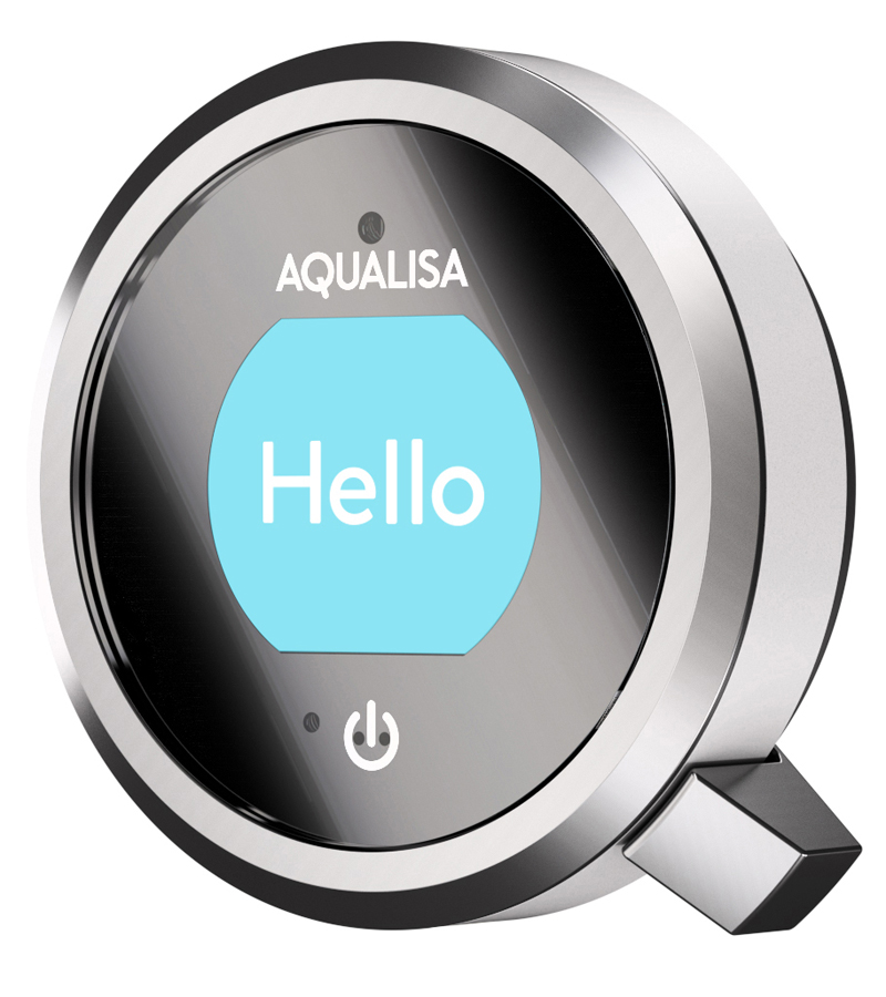
Gaining more control over our homes is a theme likely to dominate the coming years. Already prevalent in heating, lighting and security, the smart revolution is also taking place in the bathroom. One solution for showering is the Aqualisa’s Q digital mixer shower – designed not only to look great, but also give homeowners complete control over their showering experience.
Q comes with a full colour display and a number of pre-set modes from which users can select their desired experience. Eco, Sport and Family come pre-set but, by using the ‘My Q’ feature, users can also set their own preferred options – a combination of flow, duration, temperature and outlet.
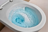
Tapping into the growing interest in resource use, Q features a proximity sensor designed to reduce water usage. Called ‘Water Save’ the flow automatically reduces when a user steps away from the shower, and returns to the original flow when the user step back in front of it – although this feature is not compatible with combi water systems.
Q is available for high pressure, combi boiler or gravity water systems with single or dual shower head configurations available, making it suitable for a wide variety of applications.
INSTALLATION GUIDE
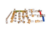
Step 1: Check you have all the pack contents

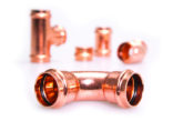
Step 2: Smart valve set up
Choose a convenient location for the Aqualisa smart valve; this must be made accessible for future servicing. The smart valve can be sited up to 10 metres from the Q control in locations such as the loft, under a bath or in an airing cupboard. Secure the smart valve and connect the hot and cold pipes.
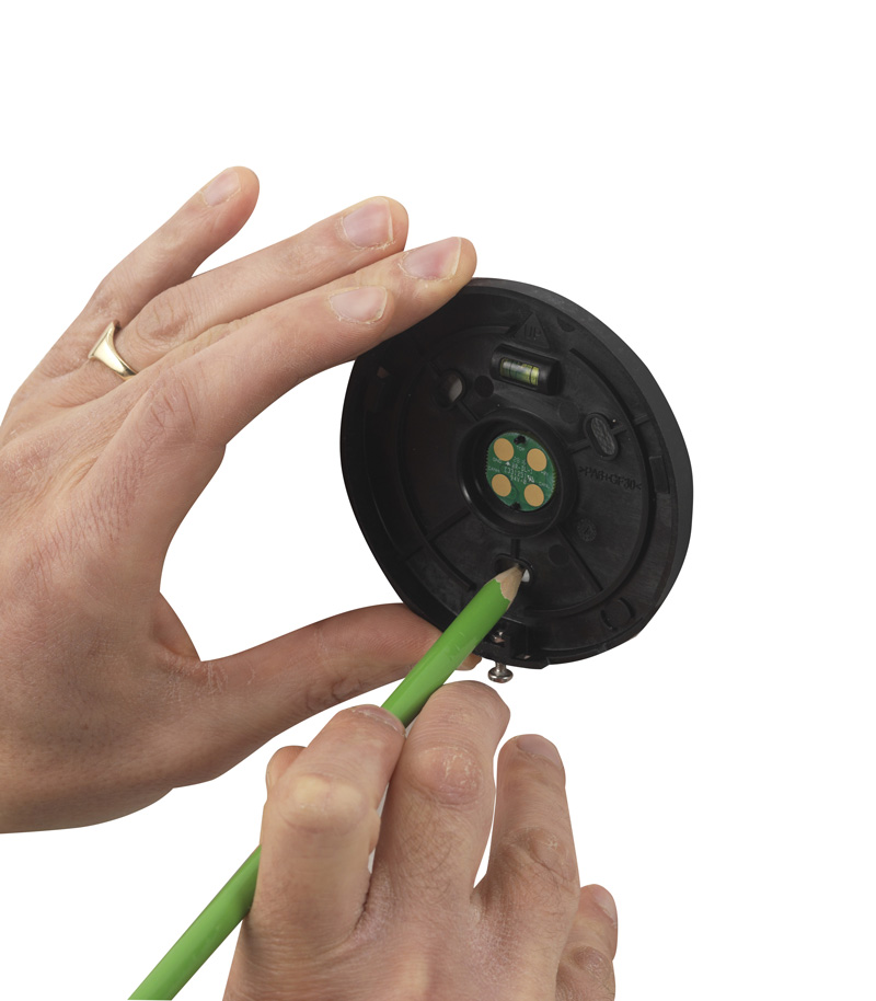
Step 3: Control positioning
Using a spirit level, attach the template provided, locate the rail and control, position, and drill where stated. It is important to note that the Aqualisa Q controller must be of a suitable height for all members of the household. The proximity sensor on the system will not be able to activate itself otherwise.
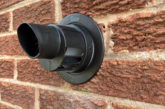
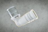
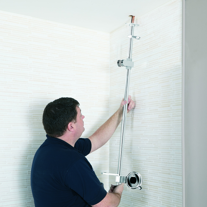
Step 4: Rail installation
Drill a hole in the ceiling of about 30 to 40mm in diameter. Feed the data cable followed by the rail assembly (that contains the supply pipe) through the hole in the ceiling. Then secure to the finished wall with the screws provided.
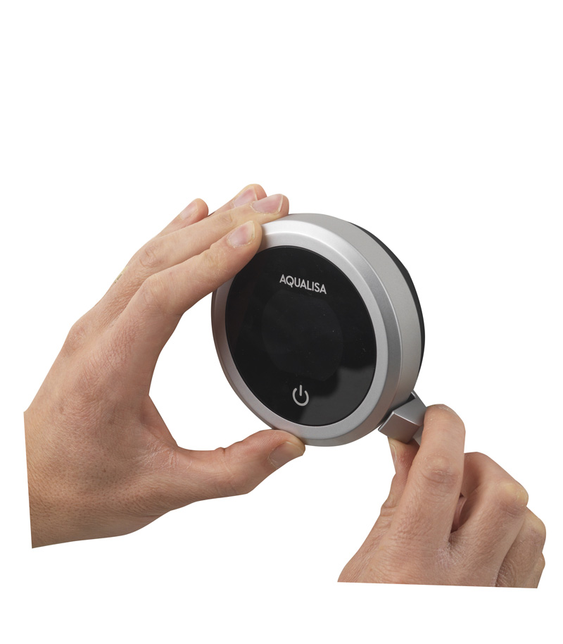
Step 5: Fitting the control
Attach the rail to the wall as directed, and fit the Q control. The control should be fitted with the power symbol at the seven o’clock position. Gently apply pressure to the screen with one hand, and use the other hand to rotate the controller with the Q lever until it fits into place.
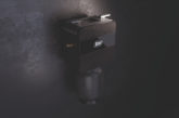
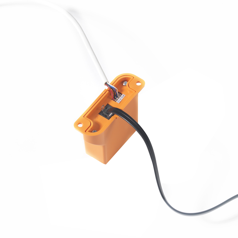
Step 6: Connecting the CANBUS converter
Remove the top case of the Q smart valve and insert the 500mm black CANBUS data cable into the joist/board with self-tapping screws provided. Open the cable connections to the CANBUS with the removal tool provided and connect the 10m data cable to the CANBUS converter box, following the wiring order shown on the label. Secure the CANBUS converter box.
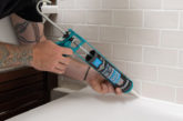
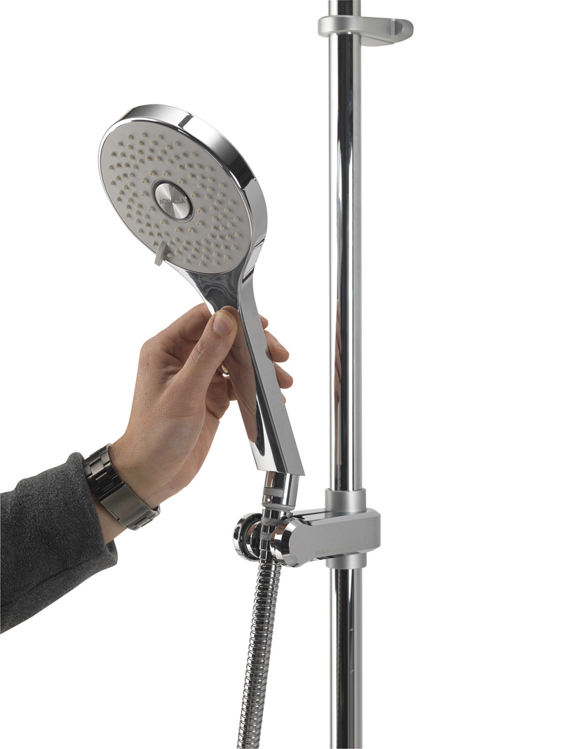
Step 7: Attaching outlets
Flush water through the outlet before connecting to the hose or handset. Use the pivot hose connector to secure the components and lock them into position. Attach carefully to the rail.
Step 8: Configuration
The shower is now ready to use (once the supplies are switched on). The Q controller can then be easily configured, where a preferred first and secondary outlet can be selected.
Full guidance is available here