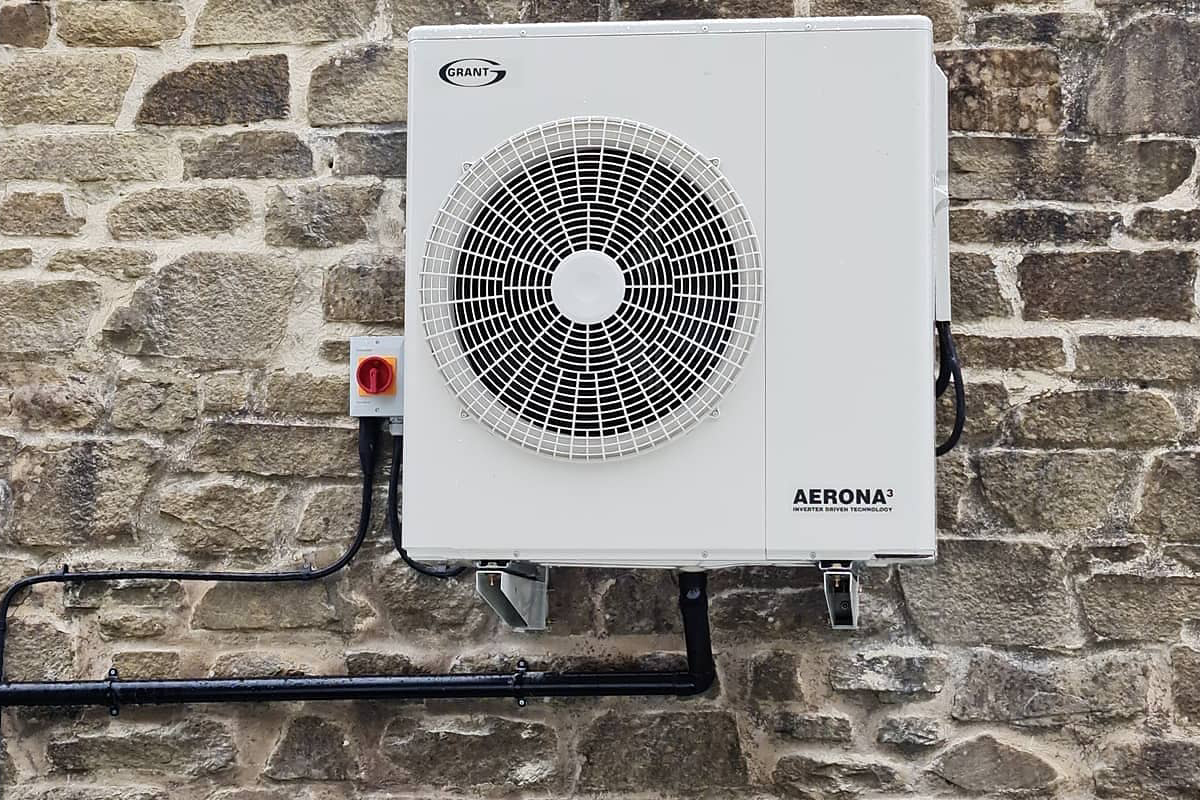
Heat loss calculations are a key part of getting any heating installation right, particularly air source heat pumps (ASHPs); essential for ensuring optimum efficiency and end user comfort. Since June, room by room heat loss calculations are now required to meet Part L Building Regulations. Griff Thomas, MD for renewables training provider, GTEC, explains.
The success of the heat pump rolls out lies in more than just their cost and availability. Consumer experience is key, so ensuring this relatively ‘new’ contributor to home heating runs efficiently and effectively is essential to widespread take-up, and also vital to meeting the updated version of Part L of the Building Regulations.
What to consider?
In the past, heat loss calculations for gas and oil boilers have been a fairly loose affair, focussing on ‘average houses’ and numbers of radiators. Fossil fuel boilers are traditionally oversized to account for this lack of accuracy.
Under Part L, this approach does not meet the regulations. Calculating heat loss on a room by room basis is required, taking into account the fabric of the building, including U values (how quickly and at what rate a building material will conduct heat) of walls, floors, roof insulations, windows and doors, as well as the size of the rooms.
The heat loss calculation looks at the space that needs heating and the potential of the building to retain heat, factoring in a number of other variables:
- Air change rates
- Expected comfort temperatures
- Lowest temperature expected in winter for that area
Heat loss calculations are designed so that you can correctly specify the heat pump, radiators/underfloor heating and a cylinder, or check how existing pipework and heat emitters will perform alongside a new system. Any short cuts could lead to insufficient heating, cold rooms and high energy bills.
One size doesn’t fit all
As mentioned, under Part L, heat loss calculations need to be accurate, so heat pumps must be selected as closely as possible to the demand. Most heat pumps are tested at an ambient temperature of 7°C and a flow temperature of 35°C.
Consider your area – Scotland has statistically much lower winter temperatures than the South East, for example. A 13kW ASHP under ‘standard’ conditions would provide significantly less output at -2°C with a flow temperature of 55°C.
- Output too low = a large bill and a cold house
- Output too high = the system could be prone to short cycling – turning on and off too often – which could lead to poor efficiencies and faults.
Cylinder sizing
In a heat pump system, water is stored at the lowest possible temperature to get the best efficiency. Despite the often scalding temperatures associated with ‘traditional’ heating systems, for most people, 40°C is plenty hot enough for water coming out the tap. Storing it at 45°C will allow for heat loss as it travels through the pipes.
To meet the new requirements for low temperature water, cylinders will need to be up-scaled to account for reduced thermal mass.
While there is undoubtedly more to consider, better sized systems will result in greater carbon reductions and happier customers across the board.
Heat loss calculation support
Many of the boiler and heat pump manufacturers offer support calculating heat losses relating to their specific products and MCS has created a heat pump calculation tool for MCS certified installers: mcscertified.com/mcs-launch-new-improved-heat-pump-calculator/
Elements of the heat loss calculation
Fabric losses:
- U value = thermal conductivity of the fabric (W/M²/°K)
- A = area (m²)
- ∆T = temperature difference between inside and outside
The fabric loss (watts) is calculated by multiplying these three factors together (U x A x ∆T).
Ventilation losses:
- V = volume of the room or building (m³)
- N = air change rate per hour, dependent on the room type and age of the property
- ∆T – temperature difference between inside and outside
- 33 – the factor for the specific heat and density of air
The ventilation loss (watts) is calculated by multiplying these four factors together V x N x ∆T x 0.33.