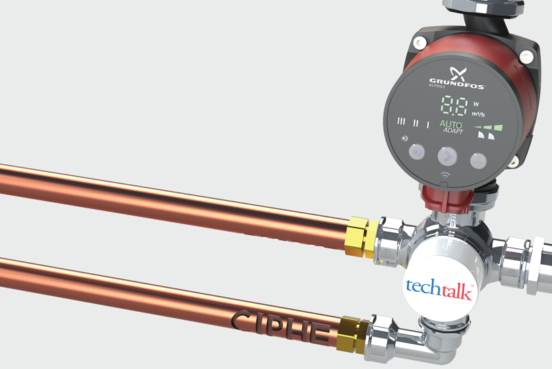
Paul Harmer, Technical Director at the CIPHE, discusses the potential for pressure loss in underfloor heating (UFH) systems if due care and consideration isn’t applied at the design stage before installation.
Over many years of designing UFH systems, I have always considered the effect on pressure loss through the UFH manifold and thermostatic mixing valve. However, designers and installers have fallen prey to this common mistake, whereby components are overlooked at the design stage. This ultimately then leads to an undersized pump, hence a system not being fit for purpose.
The problem stems from existing design guides on the market, which tend not to raise the potential for pressure losses through components such as mixer valves. Therefore, it is important to be aware of these issues and demonstrate the inherent risks of overlooking restrictions to flow.
Calculating pressure loss
Before commencing a UFH system design, the designer would normally stipulate the maximum permissible pressure loss per circuit – for example, 20 kPa or 20,000 Pa. In addition to this, the designer would also need to calculate the pressure loss through the mixer valve, manifold and isolators at the specified design flow rate.
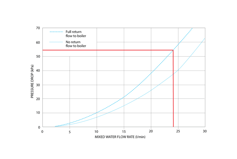
The design flow rate is the total flow rate of all of the UFH circuits added together – for example, a 12 port manifold with a flow rate of 2l/min per circuit (24l/min total). This total flow rate is used to calculate the pressure loss at both the manifold and thermostatic mixing valve. A typical UFH thermostatic mixing valve may have a pressure loss of 55 kPa with a flow rate of 24 l/min (figure 1) and 11 kPa for the isolators and manifold.
Do the math
Once the largest pressure loss has been calculated via the UFH circuit loop at 20 kPa, the pressure loss through the 12 port manifold and isolators 11 kPa and the pressure loss through the thermostatic mixing valve 55 kPa, there is a total pressure loss of 86 kPa. With this in mind, it is possible to plot the duty point onto a Grundfos UPS2 15/50/60 [figure 2] using the following data; pressure loss 86kPa, flow rate 24 l/min.
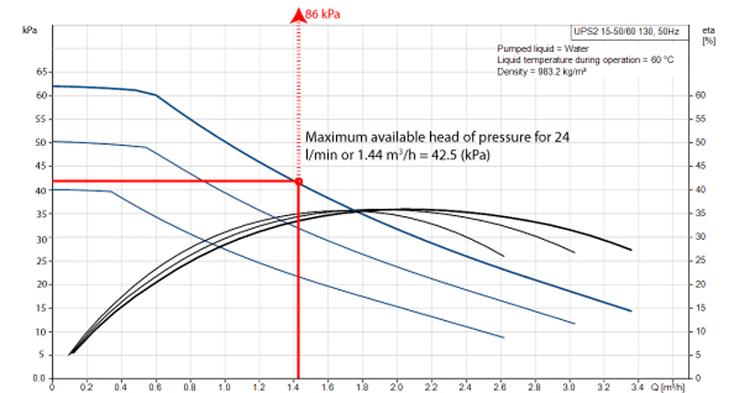
It doesn’t take long to realise that, when designing a UFH system with manifolds greater than 10 ports, the integral pump supplied with the unit may not be capable of delivering enough heat to the heat emitter. Therefore it may be difficult for the installer to diagnose a UFH system that is suffering from a lack of available pump pressure. For instance, the installer may suspect that air in the system is preventing the flow meters from rising, or that the correct UFH floor construction has not been selected.
Getting it right
When fault finding, engineers must always take time to reflect and analyse any assumptions. Being able to diagnose why an issue is taking place needs sound technical understanding, in addition to a common sense approach. Luckily there are resources which can help, such as techtalk videos from the CIPHE.
Members and non-members alike can take advantage of these techtalks, which explore issues in more detail – from covering technical aspects to how to manage expectations when discussing problems. Such as if the consumer may believe their UFH system is faulty, when it could be down to the wrong system being chosen for the application, or that pressure issues are down to an undersized pump which needs replacing.
In conclusion, it is down to UFH designers, installers and engineers to consider at every stage where due attention needs to be paid before installing a system and what to check if things do go wrong. With the right resource and expertise through industry bodies like the CIPHE, professionals are in good hands when they choose to either upskill or refresh existing knowledge.
The CIPHE will soon be sharing new techtalks on underfloor heating and controls in conjunction with Polypipe and RWC. To keep up to date with these and more techtalks from the CIPHE, subscribe to the Institute’s YouTube channel. For membership enquiries, contact the team via email: [email protected] or call 01708 472791


