Water source heat pump systems are becoming increasingly popular, but one lesser known water source application is open loop systems. Kensa gives an example of such a system being installed in a timber frame home in St Austell, Cornwall.
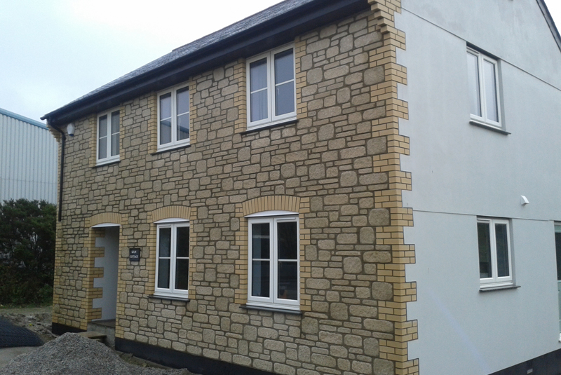
Mr Scott was determined that his new detached three-bed timber frame home in St Austell, Cornwall would utilise renewable technology to benefit from the reduced running costs and income available through the Domestic Renewable Heat Incentive (RHI).
After researching ground source heat pumps Mr Scott discovered Kensa Heat Pumps, who happened to be based just a few miles down the road from his project!
Mr Scott was aware that ground source heat pumps can extract heat from water sources as well as the ground, and as he had a stream, measuring three feet in width and six inches deep, on his land, he approached Kensa to see if this could act as his free heat source.
Mr Scott said: “As the home owner, designer and project manager, I knew what I wanted to achieve. I researched the internet and found the Kensa information very helpful, and we like to support local businesses whenever possible.
“Heat pump systems can be a bit daunting at first, but I found an installer with the required experience and willing to work with me on the design to meet our needs, and Kensa helped by providing any information requested.”
Mr Scott’s installer, Ecodragon South West, utilised Kensa’s MCS Umbrella service to deliver an RHI eligible scheme that makes use of the stream water as the primary source of heat for his Kensa ground source heat pump. Using an open loop design the stream is partially diverted into a well, where the liquid is then passed through a plate heat exchanger, which extracts the heat from the water and feeds this heat into the ground source heat pump, with the cold stream water then discharged back into the stream.
Kensa’s Technical Sales Support & Commissioning Engineer, Darren Veal, provides specialist insight into the technical steps taken to use a slow flowing stream as a heat source for a Kensa heat pump: “A simple measurement of flow was taken from the stream which proved to be enough to deliver the required heat load of the proposed new build property.
“At two foot away from the stream a chamber was constructed from two concrete rings which were sunk to approximately three feet below the stream water level. This created a well to which a flow of water from the stream could be diverted into. The well cover was at the elevated bank level making the chamber an overall depth of approximately two metres.
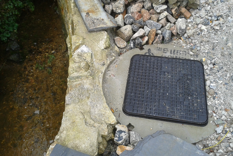
“The flow from the stream was diverted into the well by creating a small concrete channel running at approximately 45 degrees to the river bank and facing upstream. At the stream end, fins were fitted to the opening to limit any debris entering the chamber of water. A return flow pipe was fitted to the well on the downstream side to allow the stream water to continue back into the stream and carry on its natural course. Efforts were taken to minimise energy consumption in pumping the stream water with an efficiently selected pump, and use of gravity return to assist the pumping efficiency. A flow-switch detects heat pump flow and controls the primary stream water pump automatically.
“As the new build was progressing, two 32mm flexible pipes were taken from the well into the existing garage, along with a small duct for a cable. Two more pipes and cable duct were then taken back in to the main house where the heat pump was to be located.
“The house was eventually built, and the Kensa 6kW Single Compact ground source heat pump arrived on site.
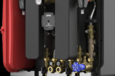
“In the garage a plate heat exchanger was fitted to the two pipes in from the well and the two back out to the heat pump. A small submersible pump was fitted in the well and located approximately one foot from the bottom to make sure no sand or silt would be sucked into the heat exchanger.
“The heat pump was fitted and the pipe work between the heat pump and plate heat exchanger was filled and tested with water and antifreeze. The heating system and hot water cylinder was installed and ready to go. The electrician made the final connections to the heat pump and submersible pump making sure that the submersible pump was switched with the ground side pump in the heat pump. This means that there will always be flow available across the plate heat exchanger before the delayed start of the compressor.
“The unit was switched on and a call for heat was activated. The ground and submersible pumps came on together and the compressor followed. The system has been working successfully for a year now and the end user is extremely satisfied. Once every six months the end user blocks the flow into the concrete channel, lifts the lid on the well and drops in a small submersible drainage pump capable of removing any silt that may have settled in the bottom of the well, this usually runs for ten minutes, following which, the well can be inspected and cleaned if required. Also the plate heat exchanger can be reverse flushed with clean water by disconnecting the well pump and connecting a garden hose to a valve on the heat exchanger outlet.”
Mr Scott commented: “We expect to be meeting in excess of 80% of our energy needs with our ground source heat pump and solar PV system. Kensa has been responsive and very helpful at every step of the process, including the application for the RHI. As an engineer it was pleasing to locate a company who had technical staff and support I could discuss my project with directly.”